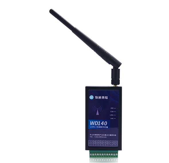
supports LORA or 4G wireless serial port transpare
HW parameters: 1 channel 232/485 serial port, 2AI-1DI-1DO and other multi-channel IO
Networking function: CAT1 4G, high power LORA (433MHZ, 915MHZ)
Acquisition function: support acquisition of analog quantity, digital quantity acquisition, support fast pulse counting
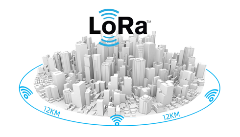
Local transparent transmission: realize wireless data transparent transmission within 12KM through LORA
Cloud access: realize remote wireless data monitoring with cloud platform through 4G
Application scenarios: factories, mines, oil fields, water conservancy, agriculture, ports, etc.

Rich IO acquisition interface
Supports 2 channels of 12-bit high-precision analog inputs, supports 1 channel of digital input and 1 channel of digital output (2AI, 1DI, 1DO), supports current type and voltage type, supports multiple ranges and multiplier calculations; supports 1 channel of dry and wet contact optional 0~60V digital input (default dry contact, support counter function); support 1 channel of optocoupler isolated transistor output;

Wireless LORA transmission function
Built-in high-power, long-distance LORA transmission chip, the transmit power can reach 30dbm, and the maximum support 12KM distance transmission; support 410~493MHz and 850~930MHz optional frequency bands, available at home and abroad;
flexibly configure LORA channels, Parameters such as power and air rate; support the setting of maximum frame length and timeout time, suitable for various data packets and corresponding speed scenarios

Standard Modbus RTU protocol
Support standard Modbus RTU protocol for local IO control and data acquisition

Wireless 4G data to the cloud
Support uploading serial port and IO data to various cloud platforms and systems through MQTT protocol through 4G network

Wireless transparent transmission
Support wireless transparent transmission of 232 or 485 serial ports, support point-to-point, point-to-multipoint data transparent transmission, support interference-free data transparent transmission of coexistence of different systems

High reliability industrial grade design
1)6~35V wide voltage design, -40~+85℃ wide temperature design;
2)Isolated RS232 or RS485 design, 15KV ESD protection;
3)Adopt optocoupler isolated digital input, precise reference voltage and high reliability relay design;
| Hardware Specifications | ||
|---|---|---|
| Hardware platform | CPU core | 32-bit Arm Cortex-M4 |
| Interface features | Power interface | DC 6V-35V (terminal) |
| Serial interface | 1 serial port (RS232/RS485), 15KV ESD protection, 9600~115200bps, default 19200 | |
| Analog input |
2 AIs with 12-bit acquisition accuracy (current type and voltage type are optional) Current type 4~20mA, 0~20mA Voltage: 0~5V, 0~10V, etc. |
|
| digital input | 1 channel optocoupler isolation 0~60V input DI, support counter function (default dry contact) | |
| digital output | 1 channel optocoupler isolated digital output DO, less than 1A load | |
| Antenna connector | LORA Antenna: SMA x 1, 4G Antenna: SMA x 1 | |
| SIM card holder | In-line card slot* 1 (medium card) | |
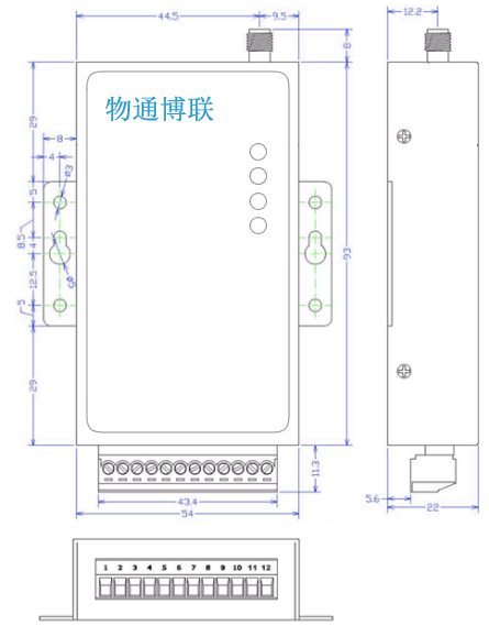
| Terminals | 12*3.5mm | |
| LORA (optional) | Working frequency | 410~493MHz or 850~930MHz optional |
| Receive sensitivity | 150dBm | |
| transmit power | 22dBm (maximum 30DB) | |
| Communication distance | 12KM (recommended indoor 1~2KM, outdoor 4~6KM) | |
| air rate | 0.48Kbps~62.5Kbps (up to 300Kbps) | |
| Emission current | 650mA | |
| LORA channel | Configurable | |
| 4G (optional) | network standard | LTE Cat1, the maximum downlink rate is 10Mbps, and the maximum uplink rate is 5Mbps |
| Mechanical properties | Dimensions | 93x54x22mm |
| Installation method | Panel Mount | |
| shell | black shell | |
| Protection class | IP30 | |
| Cooling method | Fanless cooling | |
| weight | 260g | |
|
equipment power |
Standby power | 200mA-240mA@12V |
| Working power | 250mA-290mA@12V | |
| peak power | 300mA@12.0V | |
| environment humidity | environment humidity | 5 %~ 95% (no frosting) |
| storage temperature | -40℃~ 85℃ | |
| Operating temperature | -40℃ ~ 85℃ | |
| indicator light | PWR | Power indicator display |
| WITH | Serial port status light display | |
| LORA | LORA indicator | |
| LIVE | Running status light display | |
| Modbus address mapping table | ||
|---|---|---|
| category | project | address |
| Analog input sample value | AI0~AI1 |
40000, 40001 (unsigned integer) 30000, 30001 (unsigned integer) |
| Analog input real value | AI0~AI1 |
40050, 40052 (float) 30050, 30052 (float) |
| digital input | DI0 | 10000 (switch value) |
| digital output | DO0 | 00000 (switch value) |


| Hardware selection | |
|---|---|
| order number |
WD140- |
| N (uplink network) | L (with LORA module) / G (with 4G module CAT1) / W (with WIFI module, under development*) |
| I (IO model) | M0211 (M means module, 0 means no AO, 2 means 2 AI, 1 means 1 DI, 1 means 1 DO) |
| S (serial port type) | -232: RS232 serial port; -485: RS485 serial port |
| T (extension module) | -16TF (16GB TF card), -16SSD (16GB SSD hard disk), -GPS (with positioning) |
| Example |
WD140-LM0211-485 (domestic frequency band: 410~493MHz LORA, 485 serial port) WD140-GM0211-485 (domestic frequency band: 4G CAT1 , 485 serial port) WD190 -LM0211-485 (domestic frequency band: 850~930MHz, 22dbm, 485 serial port) |


 Go Top